What components and modules do inductor symbols contain?
What Components and Modules Do Inductor Symbols Contain?
I. Introduction
Inductors are fundamental components in electrical circuits, playing a crucial role in various applications, from filtering signals to energy storage. An inductor is essentially a passive electrical component that stores energy in a magnetic field when electrical current flows through it. Understanding the components and modules represented by inductor symbols is essential for anyone involved in circuit design or electronics. This article aims to explore the intricacies of inductor symbols, their components, and the modules associated with them.
II. Understanding Inductor Symbols
A. Basic Representation of Inductors in Circuit Diagrams
In circuit diagrams, inductors are typically represented by a standardized symbol, which consists of a series of loops or curves. The most common symbol features a simple coil shape, indicating the wire windings that create the magnetic field. However, variations exist based on the type and application of the inductor. For instance, a variable inductor may be represented with an arrow or a different notation to indicate its adjustable nature.
B. Importance of Symbols in Circuit Design and Communication
Symbols serve as a universal language in circuit design, allowing engineers and technicians to communicate complex ideas succinctly. Understanding these symbols is vital for interpreting schematics, troubleshooting circuits, and ensuring that designs meet specific requirements. Inductor symbols, in particular, convey essential information about the component's function and characteristics, making them indispensable in electrical engineering.
III. Components of Inductor Symbols
A. Core Material
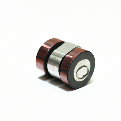
The core material of an inductor significantly influences its performance. Different core materials, such as air, ferrite, and iron, have distinct magnetic properties that affect inductance.
1. **Types of Core Materials**:
- **Air Core**: These inductors use air as the core material, resulting in lower inductance values but higher frequency response. They are often used in high-frequency applications.
- **Ferrite Core**: Ferrite cores are made from a ceramic compound that exhibits high magnetic permeability, making them suitable for high-frequency applications and reducing core losses.
- **Iron Core**: Iron cores provide high inductance values and are commonly used in power applications. However, they can suffer from saturation at high currents.
2. **Influence of Core Material on Inductance and Performance**: The choice of core material affects the inductor's inductance, efficiency, and frequency response. For example, ferrite cores are preferred in RF applications due to their low losses, while iron cores are used in power transformers for their high inductance.
B. Wire Windings
The wire windings of an inductor are another critical component that determines its characteristics.
1. **Types of Wire Used**:
- **Copper**: The most common material due to its excellent conductivity.
- **Aluminum**: Used in applications where weight is a concern, though it has higher resistance than copper.
2. **Number of Turns and Its Effect on Inductance**: The inductance of an inductor is directly proportional to the number of turns of wire. More turns increase the magnetic field strength, resulting in higher inductance. However, increasing the number of turns can also lead to higher resistance and losses.
C. Insulation
Insulation is crucial in inductors to prevent short circuits and ensure safe operation.
1. **Purpose of Insulation in Inductors**: Insulation prevents the wire windings from coming into contact with each other or the core, which could lead to failure or reduced performance.
2. **Common Insulation Materials and Their Properties**: Common insulation materials include enamel coatings, plastic, and paper. Each material has its own thermal and electrical properties, influencing the inductor's performance and reliability.
IV. Modules Associated with Inductor Symbols
A. Inductor Types
Inductors come in various types, each suited for specific applications.
1. **Air-Core Inductors**: These are simple inductors without a magnetic core, ideal for high-frequency applications due to their low losses.
2. **Iron-Core Inductors**: These inductors use iron as a core material, providing high inductance and are commonly used in power applications.
3. **Ferrite-Core Inductors**: Ferrite cores are used for their high permeability and low losses, making them suitable for RF applications.
4. **Toroidal Inductors**: These inductors have a doughnut-shaped core, which minimizes electromagnetic interference and is often used in power supplies.
B. Inductor Ratings
Understanding the ratings of inductors is essential for selecting the right component for a specific application.
1. **Inductance Value**: Measured in henries (H), this value indicates the inductor's ability to store energy in a magnetic field. Higher inductance values are typically used in power applications.
2. **Current Rating**: This rating indicates the maximum current the inductor can handle without overheating or saturating. Exceeding this rating can lead to failure.
3. **DC Resistance**: The resistance of the wire windings affects the efficiency of the inductor. Lower DC resistance is preferred for high-efficiency applications.
C. Inductor Applications
Inductors are used in a wide range of applications, including:
1. **Filtering Applications**: Inductors are commonly used in filters to block high-frequency signals while allowing low-frequency signals to pass.
2. **Energy Storage in Power Supplies**: Inductors store energy in power supply circuits, smoothing out voltage fluctuations.
3. **Oscillator Circuits**: Inductors are essential in oscillator circuits, where they work with capacitors to create oscillating signals.
4. **Transformers and Coupling Applications**: Inductors are used in transformers to transfer energy between circuits through magnetic coupling.
V. Circuit Symbols and Their Variations
A. Inductor with a Core
Inductors with a core are represented with additional markings in circuit diagrams to indicate the type of core material used, such as ferrite or iron.
B. Variable Inductors
Variable inductors are depicted with an arrow or a different symbol to indicate their adjustable nature, allowing for tuning in circuits.
C. Coupled Inductors
Coupled inductors, which consist of two or more inductors magnetically linked, are represented with additional lines or dots to indicate their coupling.
D. Inductor in Different Circuit Configurations
Inductors can be arranged in various configurations, such as series or parallel, and their symbols may vary accordingly to reflect their arrangement in the circuit.
VI. Practical Considerations in Inductor Design
A. Factors Affecting Inductor Performance
1. **Frequency Response**: The performance of an inductor can vary with frequency, making it essential to consider the operating frequency when selecting an inductor.
2. **Saturation Current**: The maximum current at which the inductor maintains its inductance is critical for ensuring reliable operation.
3. **Temperature Stability**: Inductors must be designed to operate effectively across a range of temperatures, as temperature changes can affect inductance and resistance.
B. Design Considerations for Specific Applications
1. **Size and Form Factor**: The physical size of the inductor can impact its application, with smaller inductors preferred in compact designs.
2. **Cost vs. Performance Trade-offs**: Designers must balance cost and performance, selecting materials and designs that meet budget constraints while ensuring reliability and efficiency.
VII. Conclusion
Understanding the components and modules represented by inductor symbols is vital for anyone involved in electronics and circuit design. Inductors play a crucial role in modern electronics, from filtering and energy storage to signal processing. By grasping the intricacies of inductor symbols and their associated components, engineers can design more effective and efficient circuits. As technology continues to evolve, further study and exploration in the field of inductors and their applications will remain essential for innovation in electrical engineering.
VIII. References
For those interested in delving deeper into the world of inductors and their symbols, the following resources are recommended:
1. "The Art of Electronics" by Paul Horowitz and Winfield Hill
2. "Electronic Components: A Complete Reference for Project Builders" by Mark J. Balch
3. Online resources such as educational websites, electronics forums, and manufacturer datasheets provide valuable insights into inductor design and applications.
By exploring these resources, readers can enhance their understanding of inductors and their critical role in electronic circuits.

